/**********************************************************************
【ライセンスについて】
Copyright(c) 2022 by たまねぎ
Released under the MIT license
'http://tamanegi.digick.jp/about-licence/
【スケッチの説明】
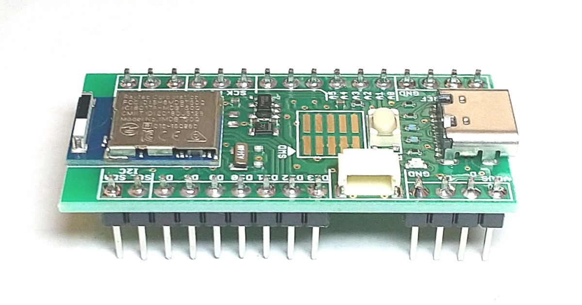
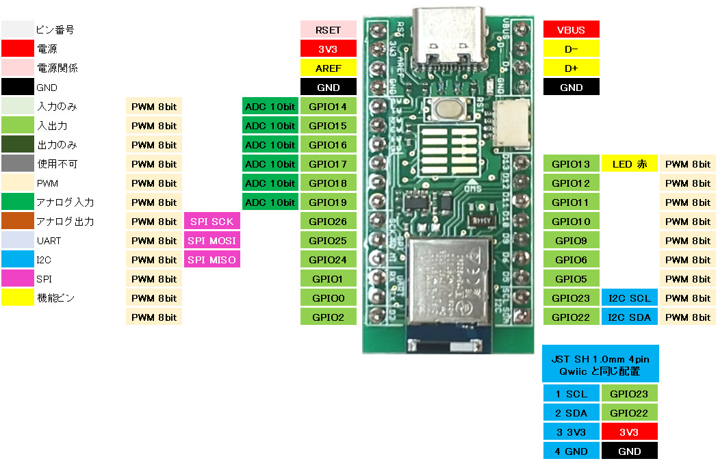
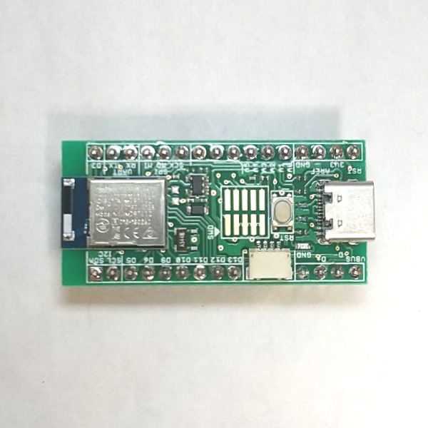
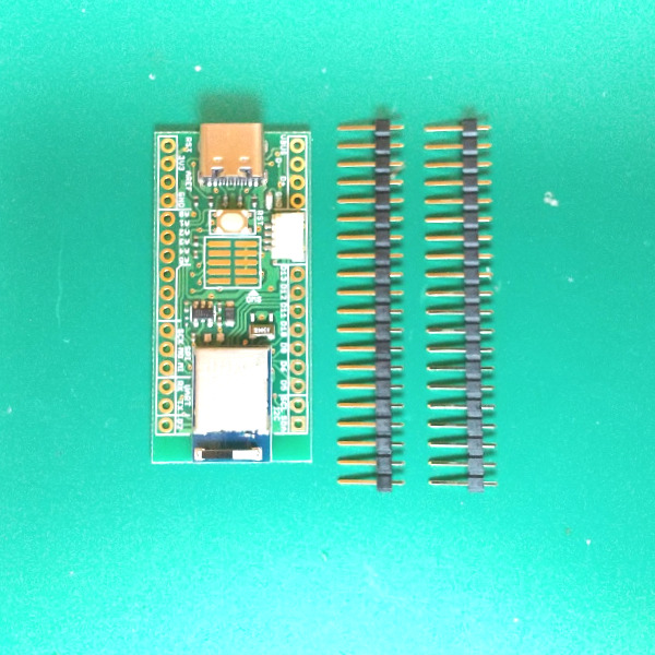
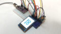
AE-nRF52840
BLEマウスとして動作します。
上下左右動作のサンプルを記載しています。
マウスのボタン、ホイール動作を含めた完成状態はこちら
/**********************************************************************
【ライセンスについて】
Copyright(c) 2022 by たまねぎ
Released under the MIT license
'http://tamanegi.digick.jp/about-licence/
【スケッチの説明】
AE-nRF52840
BLEマウスとして動作します。
ペアリング後、BLEキーボードとして動作します。
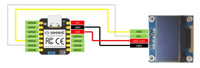
I2Cコントローラモジュールを使用したサンプルです。
ボタン右を押下するごとに "tamanegi"を一文字ずつ入力します。
ボタン左を押下すると"TAMANEGI"をまとめて入力します。
I2Cコントローラモジュールは創作物でこちらで紹介しています。
【準備】
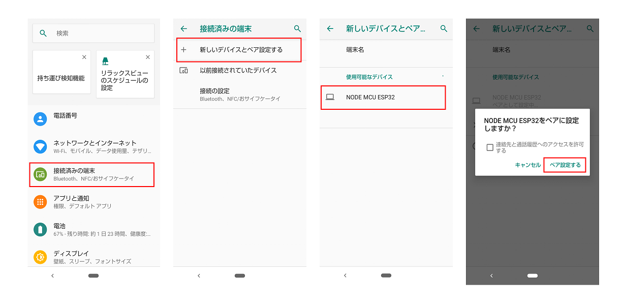
スケッチ書き込み後は、スマートホン、タブレット、ノートPC、またはBluetoothレシーバとペアリングをしてください。
Qwiicコネクタより、I2Cコントローラモジュールを接続します。
【バージョン情報】
2023/3/4 : 新規
**********************************************************************/
#include <bluefruit.h>
#include <Wire.h>
BLEDis bledis;
BLEHidAdafruit blehid;
bool hasKeyPressed = false;
#define I2C_ADDR 0x10 //I2CコントローラモジュールのI2Cアドレスは 0x10
const char strKey[] = "tamanegi"; //1文字ずつ出力するための文字列
const char strKey2[] = "TAMANEGI";
uint iIndexKey = 0; //配列の出力インデックス
uint iSizeKey = 0; //文字列サイズの保存
bool bButtonBlueOn = false; //ボタン押下状態の保存
bool bButtonBlackOn = false;
void setup()
{
Bluefruit.begin();
Bluefruit.setTxPower(4); // Check bluefruit.h for supported values
// Configure and Start Device Information Service
bledis.setManufacturer("Adafruit Industries");
bledis.setModel("Bluefruit Feather 52");
bledis.begin();
/* Start BLE HID
* Note: Apple requires BLE device must have min connection interval >= 20m
* ( The smaller the connection interval the faster we could send data).
* However for HID and MIDI device, Apple could accept min connection interval
* up to 11.25 ms. Therefore BLEHidAdafruit::begin() will try to set the min and max
* connection interval to 11.25 ms and 15 ms respectively for best performance.
*/
blehid.begin();
// Set callback for set LED from central
blehid.setKeyboardLedCallback(set_keyboard_led);
/* Set connection interval (min, max) to your perferred value.
* Note: It is already set by BLEHidAdafruit::begin() to 11.25ms - 15ms
* min = 9*1.25=11.25 ms, max = 12*1.25= 15 ms
*/
/* Bluefruit.Periph.setConnInterval(9, 12); */
// Set up and start advertising
startAdv();
//Qwiic I2Cコントローラモジュールとの接続
Wire.begin(); //I2Cマスター通信開始
}
void startAdv(void)
{
// Advertising packet
Bluefruit.Advertising.addFlags(BLE_GAP_ADV_FLAGS_LE_ONLY_GENERAL_DISC_MODE);
Bluefruit.Advertising.addTxPower();
Bluefruit.Advertising.addAppearance(BLE_APPEARANCE_HID_KEYBOARD);
// Include BLE HID service
Bluefruit.Advertising.addService(blehid);
// There is enough room for the dev name in the advertising packet
Bluefruit.Advertising.addName();
/* Start Advertising
* - Enable auto advertising if disconnected
* - Interval: fast mode = 20 ms, slow mode = 152.5 ms
* - Timeout for fast mode is 30 seconds
* - Start(timeout) with timeout = 0 will advertise forever (until connected)
*
* For recommended advertising interval
* https://developer.apple.com/library/content/qa/qa1931/_index.html
*/
Bluefruit.Advertising.restartOnDisconnect(true);
Bluefruit.Advertising.setInterval(32, 244); // in unit of 0.625 ms
Bluefruit.Advertising.setFastTimeout(30); // number of seconds in fast mode
Bluefruit.Advertising.start(0); // 0 = Don't stop advertising after n seconds
}
void loop()
{
char cStat = 0;
if(Wire.requestFrom(I2C_ADDR, 2) != 0)
{
cStat = Wire.read();
//右側のボタンが押されたら 押されるたびに"tamanegi"を一文字ずつキーボード出力
if((cStat & 0x08) != 0)
{
//チャタリング対策
if(bButtonBlueOn == false) //ボタンが押されていない状態から押された状態への変化を確認。キーを連発させないための処理
{
bButtonBlueOn = true; //ボタン押下フラグOn
blehid.keyPress(strKey[iIndexKey]); //一文字ずつキーボード出力
blehid.keyRelease();
iIndexKey ++;
if(strKey[iIndexKey] == 0x00)iIndexKey = 0; //NULL文字を検出したら最初から
}
}
else
{
bButtonBlueOn = false; //ボタン押下フラグをOff
}
//左側のボタンが押されたら "TAMANEGI"をまとめてキーボード出力
if((cStat & 0x04) != 0)
{
//チャタリング対策
if(bButtonBlackOn == false) //ボタンが押されていない状態から押された状態への変化を確認。キーを連発させないための処理
{
bButtonBlackOn = true; //ボタン押下フラグOn
//まとめてキー出力
for(int i = 0; i < strlen(strKey2); i ++)
{
blehid.keyPress(strKey2[i]);
blehid.keyRelease();
}
}
}
else
{
bButtonBlackOn = false; //ボタン押下フラグをOff
}
}
}
/**
* Callback invoked when received Set LED from central.
* Must be set previously with setKeyboardLedCallback()
*
* The LED bit map is as follows: (also defined by KEYBOARD_LED_* )
* Kana (4) | Compose (3) | ScrollLock (2) | CapsLock (1) | Numlock (0)
*/
void set_keyboard_led(uint16_t conn_handle, uint8_t led_bitmap)
{
(void) conn_handle;
// light up Red Led if any bits is set
if ( led_bitmap )
{
ledOn( LED_RED );
}
else
{
ledOff( LED_RED );
}
}
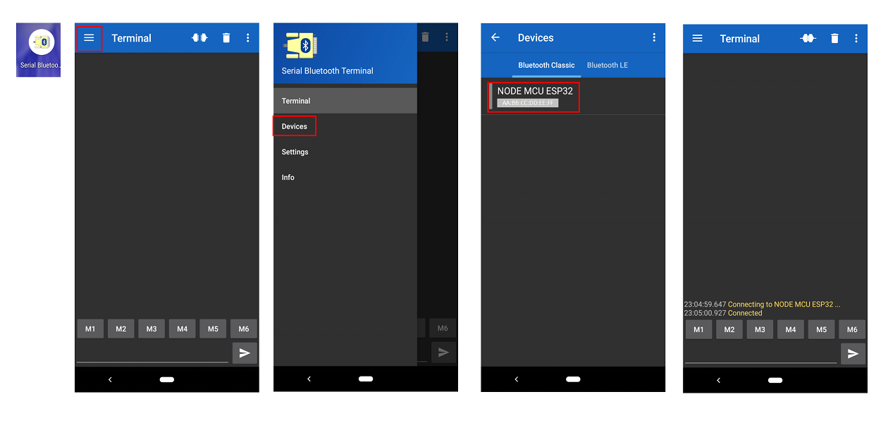
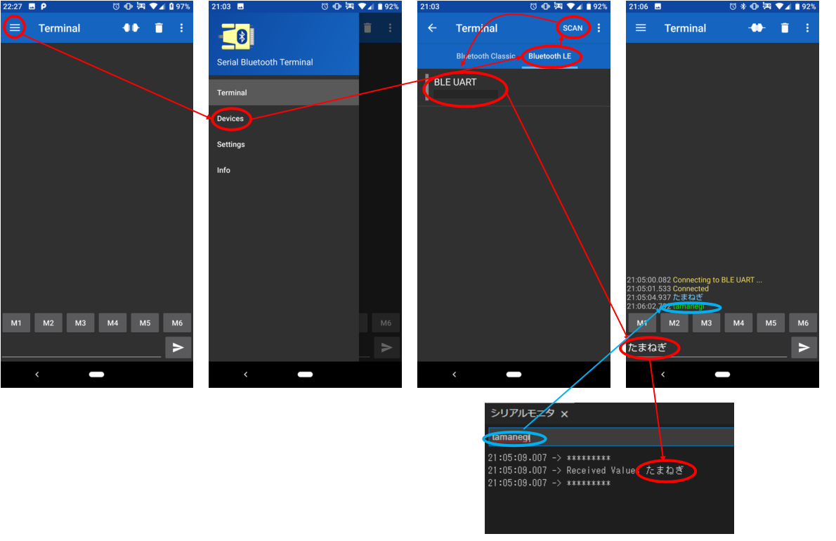
BLEUART通信をします。 パソコン側(Teraterm)から文字を入力すると、Bluetooth端末上(Serial Bluetooth Terminal)に文字が表示される。 Bluetooth端末上(Serial Bluetooth Terminal)から文字を入力すると、パソコン側(Teraterm)に文字が表示される。
準備
Bluetooth端末の通信アプリケーションとして「Serial Bluetooth Terminal」を使用します。 パソコン側は「Teraterm」を使用します。
/*********************************************************************
 This is an example for our nRF52 based Bluefruit LE modules

 Pick one up today in the adafruit shop!

 Adafruit invests time and resources providing this open source code,
 please support Adafruit and open-source hardware by purchasing
 products from Adafruit!

 MIT license, check LICENSE for more information
 All text above, and the splash screen below must be included in
 any redistribution
*********************************************************************/
#include <bluefruit.h>
#include <Adafruit_LittleFS.h>
#include <InternalFileSystem.h>

// BLE Service
BLEDfu  bledfu;  // OTA DFU service
BLEDis  bledis;  // device information
BLEUart bleuart; // uart over ble
BLEBas  blebas;  // battery

void setup()
{
  Serial.begin(115200);

#if CFG_DEBUG
  // Blocking wait for connection when debug mode is enabled via IDE
  while ( !Serial ) yield();
#endif

  Serial.println("Bluefruit52 BLEUART Example");
  Serial.println("---------------------------\n");

  // Setup the BLE LED to be enabled on CONNECT
  // Note: This is actually the default behavior, but provided
  // here in case you want to control this LED manually via PIN 19
  Bluefruit.autoConnLed(true);

  // Config the peripheral connection with maximum bandwidth
  // more SRAM required by SoftDevice
  // Note: All config***() function must be called before begin()
  Bluefruit.configPrphBandwidth(BANDWIDTH_MAX);

  Bluefruit.begin();
  Bluefruit.setTxPower(4);    // Check bluefruit.h for supported values
  //Bluefruit.setName(getMcuUniqueID()); // useful testing with multiple central connections
  Bluefruit.Periph.setConnectCallback(connect_callback);
  Bluefruit.Periph.setDisconnectCallback(disconnect_callback);

  // To be consistent OTA DFU should be added first if it exists
  bledfu.begin();

  // Configure and Start Device Information Service
  bledis.setManufacturer("Adafruit Industries");
  bledis.setModel("Bluefruit Feather52");
  bledis.begin();

  // Configure and Start BLE Uart Service
  bleuart.begin();

  // Start BLE Battery Service
  blebas.begin();
  blebas.write(100);

  // Set up and start advertising
  startAdv();

  Serial.println("Please use Adafruit's Bluefruit LE app to connect in UART mode");
  Serial.println("Once connected, enter character(s) that you wish to send");
}

void startAdv(void)
{
  // Advertising packet
  Bluefruit.Advertising.addFlags(BLE_GAP_ADV_FLAGS_LE_ONLY_GENERAL_DISC_MODE);
  Bluefruit.Advertising.addTxPower();

  // Include bleuart 128-bit uuid
  Bluefruit.Advertising.addService(bleuart);

  // Secondary Scan Response packet (optional)
  // Since there is no room for 'Name' in Advertising packet
  Bluefruit.ScanResponse.addName();

  /* Start Advertising
   * - Enable auto advertising if disconnected
   * - Interval:  fast mode = 20 ms, slow mode = 152.5 ms
   * - Timeout for fast mode is 30 seconds
   * - Start(timeout) with timeout = 0 will advertise forever (until connected)
   *
   * For recommended advertising interval
   * https://developer.apple.com/library/content/qa/qa1931/_index.html
   */
  Bluefruit.Advertising.restartOnDisconnect(true);
  Bluefruit.Advertising.setInterval(32, 244);    // in unit of 0.625 ms
  Bluefruit.Advertising.setFastTimeout(30);      // number of seconds in fast mode
  Bluefruit.Advertising.start(0);                // 0 = Don't stop advertising after n seconds
}

void loop()
{
  // Forward data from HW Serial to BLEUART
  while (Serial.available())
  {
    // Delay to wait for enough input, since we have a limited transmission buffer
    delay(2);

    uint8_t buf[64];
    int count = Serial.readBytes(buf, sizeof(buf));
    bleuart.write( buf, count );
  }

  // Forward from BLEUART to HW Serial
  while ( bleuart.available() )
  {
    uint8_t ch;
    ch = (uint8_t) bleuart.read();
    Serial.write(ch);
  }
}

// callback invoked when central connects
void connect_callback(uint16_t conn_handle)
{
  // Get the reference to current connection
  BLEConnection* connection = Bluefruit.Connection(conn_handle);

  char central_name[32] = { 0 };
  connection->getPeerName(central_name, sizeof(central_name));

  Serial.print("Connected to ");
  Serial.println(central_name);
}

/**
 * Callback invoked when a connection is dropped
 * @param conn_handle connection where this event happens
 * @param reason is a BLE_HCI_STATUS_CODE which can be found in ble_hci.h
 */
void disconnect_callback(uint16_t conn_handle, uint8_t reason)
{
  (void) conn_handle;
  (void) reason;

  Serial.println();
  Serial.print("Disconnected, reason = 0x"); Serial.println(reason, HEX);
}


コメント