Arduino環境で使用できるマイコンの中でも安く使えるマイコンを紹介します。
今回Luat OSのESP32C3 基本のDigital, Analog入出力、UART, I2C, SPI通信機能を使ってみました。
紹介するもの
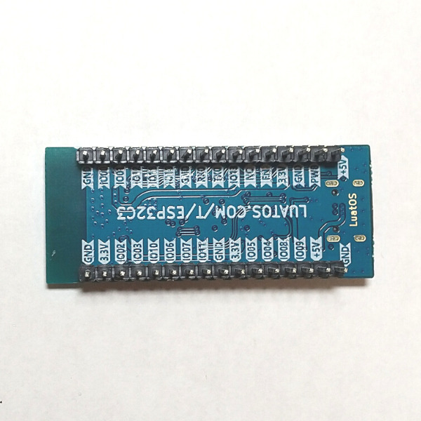
Luat OS ESP32C3
特徴
Ali Expressでの購入になりますが、200~300円台で購入できる安さ。
WifiとBTの機能はありますが、技適未対応です。(当サイトではこの製品の無線を使用しないこととします)
同基板にはUSBシリアルチップが搭載されていないモデルもあります。
今回はシリアルチップ搭載モデルを使用します。
(非搭載モデルでもスケッチの書き込みはできるはずですが、COM通信はGPIOピンのみになると思います。)
| 接続 | Type C |
| CPU | C3 RISC-V 160MHz |
| フラッシュMemory | 4MB |
| GPIO | 17(2本は実装LEDと共通) |
| ADC | 5 (12bit 0 – 4095) |
| PWM | 17 (8bit 0 – 255) 同時に5個まで使用可能 |
| UART | 2(1本はスケッチ書き込み用) |
| I2C | 1 |
| SPI | 1 |
| ボタン | BOOT RESET |
| LED | 2 (赤,GP12(D4)), (赤, GP13(D5))※1 |
[2022/12/13 GPIO, PWMのピン数修正]
Luat OS ESP32C3の紹介サイトです。(中国サイトです)
ピン配置
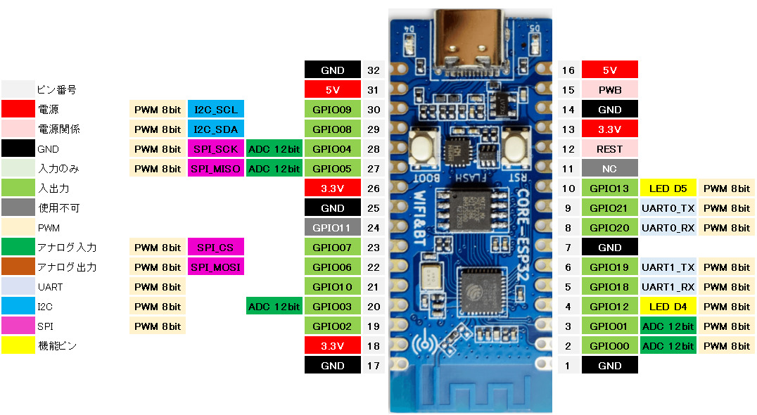
Arduino環境で”ESP32C3 Dev Module”を使用すると通信用のピン配置は当方の作成した表のようになるようですが、メーカー公開のピン配置はどの環境で使用するかの調査はしていません。
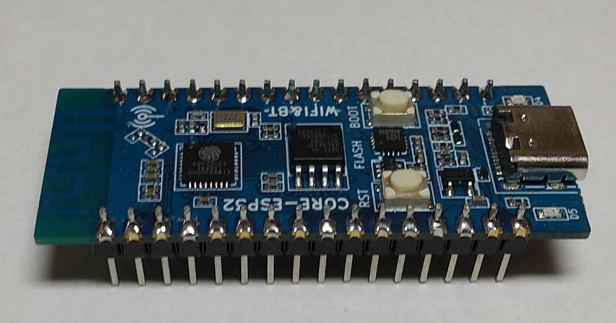
外観
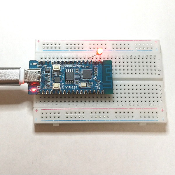
400穴ブレッドボードでは、左右2列ずつ使用することができます。

使ってみて
ピンもRP2040系のような設定は不要で普通に使うことができるので、高速処理ができるマイコンでありながら価格面でも躊躇なく使用することができます。
気になる点としてはLEDとGPIOピンが同じ配線なので、GP12, GP13を使用するとLEDが連動して点滅するのが気になります。
また、GP12,13を使用していなくても、なぜかLED(GP12, GP13)が輝度半分程度で点灯します。
意図的にLED(GP12, GP13)の出力をLOWにするスケッチを書き込むことで消灯できます。
ESP32 C3搭載、小型の基板WeAct ESP32-C3を紹介しています。
技適対応 ESP32-C3 M5STAMP C3 はこちら
準備
ライブラリ
ボードライブラリ
Arduino IDEのボードマネージャからESP32用のライブラリのインストールとボードの選択をします。
| ボードマネージャのURL | https://raw.githubusercontent.com/espressif/arduino-esp32/gh-pages/package_esp32_index.json |
| 検索 | ESP |
| ボードライブラリ | esp32 by Espressif Systems バージョン x.x.x※ |
| 選択するボード | ツール > ボード > esp32 > ESP32C3 Dev Module |
| 変更する設定 | ツール > Flash Mode > DIO |
スケッチの書き込みはESP32 のダウンロードモードにしなくても書き込みはできます。(GPIO0 と GNDをショートさせなくてもよい)
基本スケッチ
LEDチカ
説明
基板上のLED2個を交互に点滅させます。
スケッチ
//9, 8, 4, 5, 7, 6, 10, 3, 21, 20, 13, 19, 18, 12, 1, 0 //digitalWriteで使用可能なピン

#define LED1 12       //基板実装LED1 (赤)
#define LED2 13       //基板実装LED2 (赤)

void setup()
{
  pinMode(LED1, OUTPUT);  //ピン出力設定
  pinMode(LED2, OUTPUT);
}

void loop()
{
  //実装LEDの点滅を行います。
  //片方が点灯しているときに、反対側は消灯する動作をします。
  digitalWrite(LED1, HIGH);
  digitalWrite(LED2, LOW);
  delay(500);

  digitalWrite(LED1, LOW);
  digitalWrite(LED2, HIGH);
  delay(500);
}
結果
LEDが交互に点滅しました。
GPIOピン番号の12にLEDを挿してみました。
手前のLEDと同じ番号であるため、同じタイミングで点滅を行います。
PWM
説明
PWMを使ってLEDのフェード点灯(ゆっくり点灯させる)を行います。
ピン配置上4chあるので、LED4個を点灯させます。
スケッチ
// 9, 8, 4, 5, 7     //PWM (8bit 0 - 255)

#define PWM04 8     //赤
#define PWM01 6     //緑
#define PWM03 10    //黄
#define PWM02 2     //白

void setup()
{
  pinMode(PWM04, OUTPUT);
  pinMode(PWM01, OUTPUT);
  pinMode(PWM03, OUTPUT);
  pinMode(PWM02, OUTPUT);

}

void loop()
{
  int i;

  for (i = 0; i < 256; i ++)
  {
    analogWrite(PWM04, i);
    analogWrite(PWM01, i);
    analogWrite(PWM03, i);
    analogWrite(PWM02, i);
    delay(10);
  }
}
結果
LEDが4個同時にゆっくり点灯しました。
動画で使用する保護抵抗は、机の周辺に落ちてたやつを使っているので適当です。
ピン表のPWMはGPIO8, 6, 10, 2 と記載されていましたが、それ以外でも使用できるようです。
GPIOピン番号の12にLEDを挿してみました。
手前のLEDと同じ番号であるため、同じタイミングで点滅を行います。
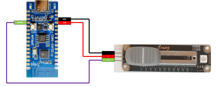
ADC
説明
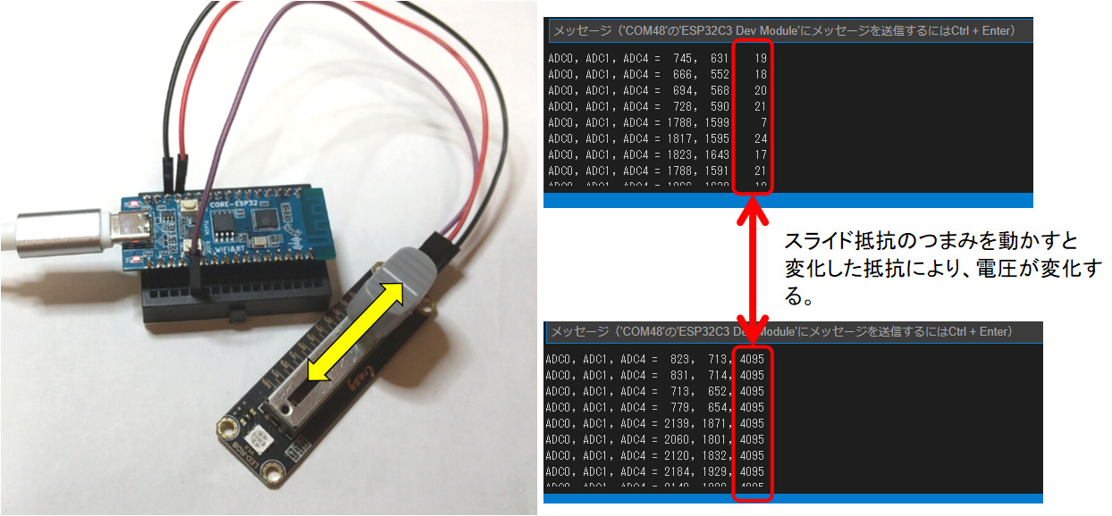
スライド抵抗通過後の電圧値を読み取ります。
配線
| ESP32C3 | 配線 | スライド抵抗 |
|---|---|---|
| 3.3V | 赤 | + |
| GND | 黒 | – |
| GPIO04 | 紫 | S |
スケッチ
// 4, 5, 3, 1, 0    //analogRead(12bit 0 - 4095)

#define PIN_ADC0 0      //ADC0
#define PIN_ADC1 1      //ADC1
#define PIN_ADC4 4      //ADC4

void setup()
{
  delay(1000);
  Serial.begin(115200);         //結果はCOMに出力

  pinMode(PIN_ADC0, INPUT);
  pinMode(PIN_ADC1, INPUT);
  pinMode(PIN_ADC4, INPUT);

}

void loop()
{
  long ADC0 = 0;
  long ADC1 = 0;
  long ADC4 = 0;

  ADC0 = analogRead(PIN_ADC0);
  ADC1 = analogRead(PIN_ADC1);
  ADC4 = analogRead(PIN_ADC4);

  Serial.printf("ADC0, ADC1, ADC4 = %4d, %4d, %4d\n", ADC0, ADC1, ADC4);
  delay(100);
}
結果
結果はADC4にスライド抵抗を接続しています。
スライド抵抗のつまみを変化させることで、A/Dの読み取り値に変化がありました。
画像の通り、スライド抵抗が1つしかないので1つずつ動作確認をしています。
接続されていないADC0とADC1は不安定な状態でノイズを拾っています。
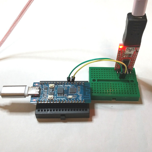
UART
説明
UART0(COM)から読み取ったデータをUART1に送信します。
UART1から読み取ったデータをUART0(COM)に送信します。
配線
| ESP32C3 | 配線 | USB-Serial |
|---|---|---|
| GPIO18 | 緑 | TX |
| GPIO19 | 黄 | RX |
スケッチ
//UART0 21(TX), 20(RX)
//UART1 19(TX), 18(RX)
void setup()
{
  Serial.begin(115200);                 //SerialオブジェクトはUART0 (COM)
  Serial1.begin(115200);                //Serial1オブジェクトはUART1
}

void loop()
{
  if(Serial1.available() != 0)          //UART1にデータがあれば、読み取った内容をUART0に送信
  {
      Serial.write(Serial1.read());
  }

  if(Serial.available() != 0)           //UART0にデータがあれば、読み取った内容をUART1に送信
  {
      Serial1.write(Serial.read());
  }
}
結果
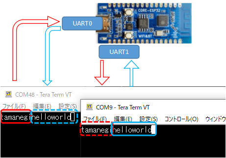
結果はTeratermを2つ起動して確認します。
1つはESP32C3(スケッチの書き込みに使用したCOM)。
もう一つはUSB-シリアルモジュールのCOM。こちらはUART1として通信します。
USBのCOMはCOM48, USBシリアルモジュールはCOM9として認識されました。
Teratermの設定はローカルエコーは有効です。
始めにCOM48の赤実線枠に”tamanegi”と入力すると、COM9の赤破線枠のように”tamanegi”と表示されました。
UART0からUART1へデータが送信されたことがわかります。
次にCOM9の青実線枠”helloworld”と入力すると、COM48の青破線枠のように”helloworld”と表示されました。
UART1からUART0へデータが送信されたことがわかります。
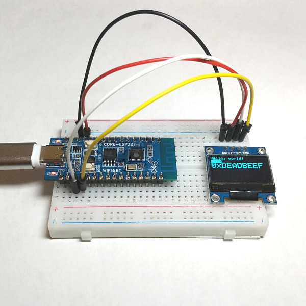
I2C(SSD1306)
説明
I2Cを使ってSSD1306(OLED 0.96inch)モニタのサンプルを動作させます。
配線
| ESP32C3 | 配線 | SSD1306(0.96inch) |
|---|---|---|
| 3.3V | 赤 | VCC |
| GND | 黒 | GND |
| GPIO09 | 白 | SCL |
| GPIO08 | 黄 | SDA |
スケッチ
Arduinoサンプルスケッチを掲載します。
ファイル(F) > スケッチ例 > Adafruit SSD1306 > ssd1306_128x64_i2c
使用しているSSD1306 OLEDのI2Cアドレスを変更して使用してください。
35行目 : 当方 0x3cで使用しているため変更しています。
/**************************************************************************
 This is an example for our Monochrome OLEDs based on SSD1306 drivers

 Pick one up today in the adafruit shop!
 ------> http://www.adafruit.com/category/63_98

 This example is for a 128x64 pixel display using I2C to communicate
 3 pins are required to interface (two I2C and one reset).

 Adafruit invests time and resources providing this open
 source code, please support Adafruit and open-source
 hardware by purchasing products from Adafruit!

 Written by Limor Fried/Ladyada for Adafruit Industries,
 with contributions from the open source community.
 BSD license, check license.txt for more information
 All text above, and the splash screen below must be
 included in any redistribution.
 **************************************************************************/

#include <SPI.h>
#include <Wire.h>
#include <Adafruit_GFX.h>
#include <Adafruit_SSD1306.h>

#define SCREEN_WIDTH 128 // OLED display width, in pixels
#define SCREEN_HEIGHT 64 // OLED display height, in pixels

// Declaration for an SSD1306 display connected to I2C (SDA, SCL pins)
// The pins for I2C are defined by the Wire-library.
// On an arduino UNO:       A4(SDA), A5(SCL)
// On an arduino MEGA 2560: 20(SDA), 21(SCL)
// On an arduino LEONARDO:   2(SDA),  3(SCL), ...
#define OLED_RESET     -1 // Reset pin # (or -1 if sharing Arduino reset pin)
#define SCREEN_ADDRESS 0x3C ///< See datasheet for Address; 0x3D for 128x64, 0x3C for 128x32
Adafruit_SSD1306 display(SCREEN_WIDTH, SCREEN_HEIGHT, &Wire, OLED_RESET);

#define NUMFLAKES     10 // Number of snowflakes in the animation example

#define LOGO_HEIGHT   16
#define LOGO_WIDTH    16
static const unsigned char PROGMEM logo_bmp[] =
{ 0b00000000, 0b11000000,
  0b00000001, 0b11000000,
  0b00000001, 0b11000000,
  0b00000011, 0b11100000,
  0b11110011, 0b11100000,
  0b11111110, 0b11111000,
  0b01111110, 0b11111111,
  0b00110011, 0b10011111,
  0b00011111, 0b11111100,
  0b00001101, 0b01110000,
  0b00011011, 0b10100000,
  0b00111111, 0b11100000,
  0b00111111, 0b11110000,
  0b01111100, 0b11110000,
  0b01110000, 0b01110000,
  0b00000000, 0b00110000 };

void setup() {
  Serial.begin(9600);

  // SSD1306_SWITCHCAPVCC = generate display voltage from 3.3V internally
  if(!display.begin(SSD1306_SWITCHCAPVCC, SCREEN_ADDRESS)) {
    Serial.println(F("SSD1306 allocation failed"));
    for(;;); // Don't proceed, loop forever
  }

  // Show initial display buffer contents on the screen --
  // the library initializes this with an Adafruit splash screen.
  display.display();
  delay(2000); // Pause for 2 seconds

  // Clear the buffer
  display.clearDisplay();

  // Draw a single pixel in white
  display.drawPixel(10, 10, SSD1306_WHITE);

  // Show the display buffer on the screen. You MUST call display() after
  // drawing commands to make them visible on screen!
  display.display();
  delay(2000);
  // display.display() is NOT necessary after every single drawing command,
  // unless that's what you want...rather, you can batch up a bunch of
  // drawing operations and then update the screen all at once by calling
  // display.display(). These examples demonstrate both approaches...

  testdrawline();      // Draw many lines

  testdrawrect();      // Draw rectangles (outlines)

  testfillrect();      // Draw rectangles (filled)

  testdrawcircle();    // Draw circles (outlines)

  testfillcircle();    // Draw circles (filled)

  testdrawroundrect(); // Draw rounded rectangles (outlines)

  testfillroundrect(); // Draw rounded rectangles (filled)

  testdrawtriangle();  // Draw triangles (outlines)

  testfilltriangle();  // Draw triangles (filled)

  testdrawchar();      // Draw characters of the default font

  testdrawstyles();    // Draw 'stylized' characters

  testscrolltext();    // Draw scrolling text

  testdrawbitmap();    // Draw a small bitmap image

  // Invert and restore display, pausing in-between
  display.invertDisplay(true);
  delay(1000);
  display.invertDisplay(false);
  delay(1000);

  testanimate(logo_bmp, LOGO_WIDTH, LOGO_HEIGHT); // Animate bitmaps
}

void loop() {
}

void testdrawline() {
  int16_t i;

  display.clearDisplay(); // Clear display buffer

  for(i=0; i<display.width(); i+=4) {
    display.drawLine(0, 0, i, display.height()-1, SSD1306_WHITE);
    display.display(); // Update screen with each newly-drawn line
    delay(1);
  }
  for(i=0; i<display.height(); i+=4) {
    display.drawLine(0, 0, display.width()-1, i, SSD1306_WHITE);
    display.display();
    delay(1);
  }
  delay(250);

  display.clearDisplay();

  for(i=0; i<display.width(); i+=4) {
    display.drawLine(0, display.height()-1, i, 0, SSD1306_WHITE);
    display.display();
    delay(1);
  }
  for(i=display.height()-1; i>=0; i-=4) {
    display.drawLine(0, display.height()-1, display.width()-1, i, SSD1306_WHITE);
    display.display();
    delay(1);
  }
  delay(250);

  display.clearDisplay();

  for(i=display.width()-1; i>=0; i-=4) {
    display.drawLine(display.width()-1, display.height()-1, i, 0, SSD1306_WHITE);
    display.display();
    delay(1);
  }
  for(i=display.height()-1; i>=0; i-=4) {
    display.drawLine(display.width()-1, display.height()-1, 0, i, SSD1306_WHITE);
    display.display();
    delay(1);
  }
  delay(250);

  display.clearDisplay();

  for(i=0; i<display.height(); i+=4) {
    display.drawLine(display.width()-1, 0, 0, i, SSD1306_WHITE);
    display.display();
    delay(1);
  }
  for(i=0; i<display.width(); i+=4) {
    display.drawLine(display.width()-1, 0, i, display.height()-1, SSD1306_WHITE);
    display.display();
    delay(1);
  }

  delay(2000); // Pause for 2 seconds
}

void testdrawrect(void) {
  display.clearDisplay();

  for(int16_t i=0; i<display.height()/2; i+=2) {
    display.drawRect(i, i, display.width()-2*i, display.height()-2*i, SSD1306_WHITE);
    display.display(); // Update screen with each newly-drawn rectangle
    delay(1);
  }

  delay(2000);
}

void testfillrect(void) {
  display.clearDisplay();

  for(int16_t i=0; i<display.height()/2; i+=3) {
    // The INVERSE color is used so rectangles alternate white/black
    display.fillRect(i, i, display.width()-i*2, display.height()-i*2, SSD1306_INVERSE);
    display.display(); // Update screen with each newly-drawn rectangle
    delay(1);
  }

  delay(2000);
}

void testdrawcircle(void) {
  display.clearDisplay();

  for(int16_t i=0; i<max(display.width(),display.height())/2; i+=2) {
    display.drawCircle(display.width()/2, display.height()/2, i, SSD1306_WHITE);
    display.display();
    delay(1);
  }

  delay(2000);
}

void testfillcircle(void) {
  display.clearDisplay();

  for(int16_t i=max(display.width(),display.height())/2; i>0; i-=3) {
    // The INVERSE color is used so circles alternate white/black
    display.fillCircle(display.width() / 2, display.height() / 2, i, SSD1306_INVERSE);
    display.display(); // Update screen with each newly-drawn circle
    delay(1);
  }

  delay(2000);
}

void testdrawroundrect(void) {
  display.clearDisplay();

  for(int16_t i=0; i<display.height()/2-2; i+=2) {
    display.drawRoundRect(i, i, display.width()-2*i, display.height()-2*i,
      display.height()/4, SSD1306_WHITE);
    display.display();
    delay(1);
  }

  delay(2000);
}

void testfillroundrect(void) {
  display.clearDisplay();

  for(int16_t i=0; i<display.height()/2-2; i+=2) {
    // The INVERSE color is used so round-rects alternate white/black
    display.fillRoundRect(i, i, display.width()-2*i, display.height()-2*i,
      display.height()/4, SSD1306_INVERSE);
    display.display();
    delay(1);
  }

  delay(2000);
}

void testdrawtriangle(void) {
  display.clearDisplay();

  for(int16_t i=0; i<max(display.width(),display.height())/2; i+=5) {
    display.drawTriangle(
      display.width()/2  , display.height()/2-i,
      display.width()/2-i, display.height()/2+i,
      display.width()/2+i, display.height()/2+i, SSD1306_WHITE);
    display.display();
    delay(1);
  }

  delay(2000);
}

void testfilltriangle(void) {
  display.clearDisplay();

  for(int16_t i=max(display.width(),display.height())/2; i>0; i-=5) {
    // The INVERSE color is used so triangles alternate white/black
    display.fillTriangle(
      display.width()/2  , display.height()/2-i,
      display.width()/2-i, display.height()/2+i,
      display.width()/2+i, display.height()/2+i, SSD1306_INVERSE);
    display.display();
    delay(1);
  }

  delay(2000);
}

void testdrawchar(void) {
  display.clearDisplay();

  display.setTextSize(1);      // Normal 1:1 pixel scale
  display.setTextColor(SSD1306_WHITE); // Draw white text
  display.setCursor(0, 0);     // Start at top-left corner
  display.cp437(true);         // Use full 256 char 'Code Page 437' font

  // Not all the characters will fit on the display. This is normal.
  // Library will draw what it can and the rest will be clipped.
  for(int16_t i=0; i<256; i++) {
    if(i == '\n') display.write(' ');
    else          display.write(i);
  }

  display.display();
  delay(2000);
}

void testdrawstyles(void) {
  display.clearDisplay();

  display.setTextSize(1);             // Normal 1:1 pixel scale
  display.setTextColor(SSD1306_WHITE);        // Draw white text
  display.setCursor(0,0);             // Start at top-left corner
  display.println(F("Hello, world!"));

  display.setTextColor(SSD1306_BLACK, SSD1306_WHITE); // Draw 'inverse' text
  display.println(3.141592);

  display.setTextSize(2);             // Draw 2X-scale text
  display.setTextColor(SSD1306_WHITE);
  display.print(F("0x")); display.println(0xDEADBEEF, HEX);

  display.display();
  delay(2000);
}

void testscrolltext(void) {
  display.clearDisplay();

  display.setTextSize(2); // Draw 2X-scale text
  display.setTextColor(SSD1306_WHITE);
  display.setCursor(10, 0);
  display.println(F("scroll"));
  display.display();      // Show initial text
  delay(100);

  // Scroll in various directions, pausing in-between:
  display.startscrollright(0x00, 0x0F);
  delay(2000);
  display.stopscroll();
  delay(1000);
  display.startscrollleft(0x00, 0x0F);
  delay(2000);
  display.stopscroll();
  delay(1000);
  display.startscrolldiagright(0x00, 0x07);
  delay(2000);
  display.startscrolldiagleft(0x00, 0x07);
  delay(2000);
  display.stopscroll();
  delay(1000);
}

void testdrawbitmap(void) {
  display.clearDisplay();

  display.drawBitmap(
    (display.width()  - LOGO_WIDTH ) / 2,
    (display.height() - LOGO_HEIGHT) / 2,
    logo_bmp, LOGO_WIDTH, LOGO_HEIGHT, 1);
  display.display();
  delay(1000);
}

#define XPOS   0 // Indexes into the 'icons' array in function below
#define YPOS   1
#define DELTAY 2

void testanimate(const uint8_t *bitmap, uint8_t w, uint8_t h) {
  int8_t f, icons[NUMFLAKES][3];

  // Initialize 'snowflake' positions
  for(f=0; f< NUMFLAKES; f++) {
    icons[f][XPOS]   = random(1 - LOGO_WIDTH, display.width());
    icons[f][YPOS]   = -LOGO_HEIGHT;
    icons[f][DELTAY] = random(1, 6);
    Serial.print(F("x: "));
    Serial.print(icons[f][XPOS], DEC);
    Serial.print(F(" y: "));
    Serial.print(icons[f][YPOS], DEC);
    Serial.print(F(" dy: "));
    Serial.println(icons[f][DELTAY], DEC);
  }

  for(;;) { // Loop forever...
    display.clearDisplay(); // Clear the display buffer

    // Draw each snowflake:
    for(f=0; f< NUMFLAKES; f++) {
      display.drawBitmap(icons[f][XPOS], icons[f][YPOS], bitmap, w, h, SSD1306_WHITE);
    }

    display.display(); // Show the display buffer on the screen
    delay(200);        // Pause for 1/10 second

    // Then update coordinates of each flake...
    for(f=0; f< NUMFLAKES; f++) {
      icons[f][YPOS] += icons[f][DELTAY];
      // If snowflake is off the bottom of the screen...
      if (icons[f][YPOS] >= display.height()) {
        // Reinitialize to a random position, just off the top
        icons[f][XPOS]   = random(1 - LOGO_WIDTH, display.width());
        icons[f][YPOS]   = -LOGO_HEIGHT;
        icons[f][DELTAY] = random(1, 6);
      }
    }
  }
}
結果
SSD1306のサンプルスケッチが動作しました。
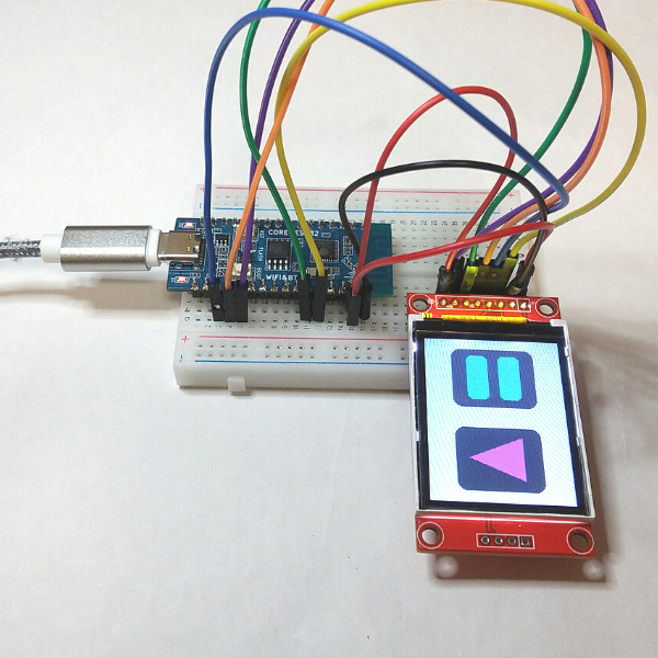
SPI(ST7735)
説明
SPIを使ってST7735(LCD 1.8inch)モニタのサンプルを動作させます。
配線
| ESP32C3 | 配線 | ST7735(1.8inch) |
|---|---|---|
| 3.3V | 赤 | VCC |
| 3.3V | 赤 | LED |
| GND | 黒 | GND |
| GPIO09 | 青 | Reset |
| GPIO08 | 橙 | AO(DC) |
| GPIO04 | 紫 | SCK |
| GPIO06 | 緑 | SDA |
| GPIO10 | 黄 | CS |
スケッチ
Arduinoサンプルスケッチを掲載します。
ファイル(F) > スケッチ例 > Adafruit ST7735 and ST7789 Library > graphicstest
配線説明通りの配線であればスケッチの変更は不要です。
使用するモニタのサイズ、ドライバが違う場合適当な初期化処理のコメントを解除してください。
/**************************************************************************
  This is a library for several Adafruit displays based on ST77* drivers.

  Works with the Adafruit 1.8" TFT Breakout w/SD card
    ----> http://www.adafruit.com/products/358
  The 1.8" TFT shield
    ----> https://www.adafruit.com/product/802
  The 1.44" TFT breakout
    ----> https://www.adafruit.com/product/2088
  The 1.14" TFT breakout
  ----> https://www.adafruit.com/product/4383
  The 1.3" TFT breakout
  ----> https://www.adafruit.com/product/4313
  The 1.54" TFT breakout
    ----> https://www.adafruit.com/product/3787
  The 1.69" TFT breakout
    ----> https://www.adafruit.com/product/5206
  The 2.0" TFT breakout
    ----> https://www.adafruit.com/product/4311
  as well as Adafruit raw 1.8" TFT display
    ----> http://www.adafruit.com/products/618

  Check out the links above for our tutorials and wiring diagrams.
  These displays use SPI to communicate, 4 or 5 pins are required to
  interface (RST is optional).

  Adafruit invests time and resources providing this open source code,
  please support Adafruit and open-source hardware by purchasing
  products from Adafruit!

  Written by Limor Fried/Ladyada for Adafruit Industries.
  MIT license, all text above must be included in any redistribution
 **************************************************************************/

#include <Adafruit_GFX.h>    // Core graphics library
#include <Adafruit_ST7735.h> // Hardware-specific library for ST7735
#include <Adafruit_ST7789.h> // Hardware-specific library for ST7789
#include <SPI.h>

#if defined(ARDUINO_FEATHER_ESP32) // Feather Huzzah32
  #define TFT_CS         14
  #define TFT_RST        15
  #define TFT_DC         32

#elif defined(ESP8266)
  #define TFT_CS         4
  #define TFT_RST        16
  #define TFT_DC         5

#else
  // For the breakout board, you can use any 2 or 3 pins.
  // These pins will also work for the 1.8" TFT shield.
  #define TFT_CS        10
  #define TFT_RST        9 // Or set to -1 and connect to Arduino RESET pin
  #define TFT_DC         8
#endif

// OPTION 1 (recommended) is to use the HARDWARE SPI pins, which are unique
// to each board and not reassignable. For Arduino Uno: MOSI = pin 11 and
// SCLK = pin 13. This is the fastest mode of operation and is required if
// using the breakout board's microSD card.

// For 1.44" and 1.8" TFT with ST7735 use:
Adafruit_ST7735 tft = Adafruit_ST7735(TFT_CS, TFT_DC, TFT_RST);

// For 1.14", 1.3", 1.54", 1.69", and 2.0" TFT with ST7789:
//Adafruit_ST7789 tft = Adafruit_ST7789(TFT_CS, TFT_DC, TFT_RST);


// OPTION 2 lets you interface the display using ANY TWO or THREE PINS,
// tradeoff being that performance is not as fast as hardware SPI above.
//#define TFT_MOSI 11  // Data out
//#define TFT_SCLK 13  // Clock out

// For ST7735-based displays, we will use this call
//Adafruit_ST7735 tft = Adafruit_ST7735(TFT_CS, TFT_DC, TFT_MOSI, TFT_SCLK, TFT_RST);

// OR for the ST7789-based displays, we will use this call
//Adafruit_ST7789 tft = Adafruit_ST7789(TFT_CS, TFT_DC, TFT_MOSI, TFT_SCLK, TFT_RST);


float p = 3.1415926;

void setup(void) {
  delay(1000);
  Serial.begin(9600);
  Serial.print(F("Hello! ST77xx TFT Test  "));
  Serial.print(TFT_CS);

  // Use this initializer if using a 1.8" TFT screen:
  tft.initR(INITR_BLACKTAB);      // Init ST7735S chip, black tab

  // OR use this initializer if using a 1.8" TFT screen with offset such as WaveShare:
  //tft.initR(INITR_GREENTAB);      // Init ST7735S chip, green tab

  // OR use this initializer (uncomment) if using a 1.44" TFT:
  //tft.initR(INITR_144GREENTAB); // Init ST7735R chip, green tab

  // OR use this initializer (uncomment) if using a 0.96" 160x80 TFT:
  //tft.initR(INITR_MINI160x80);  // Init ST7735S mini display

  // OR use this initializer (uncomment) if using a 1.3" or 1.54" 240x240 TFT:
  //tft.init(240, 240);           // Init ST7789 240x240

  // OR use this initializer (uncomment) if using a 1.69" 280x240 TFT:
  //tft.init(240, 280);           // Init ST7789 280x240

  // OR use this initializer (uncomment) if using a 2.0" 320x240 TFT:
  //tft.init(240, 320);           // Init ST7789 320x240

  // OR use this initializer (uncomment) if using a 1.14" 240x135 TFT:
  //tft.init(135, 240);           // Init ST7789 240x135

  // OR use this initializer (uncomment) if using a 1.47" 172x320 TFT:
  //tft.init(172, 320);           // Init ST7789 172x320

  // SPI speed defaults to SPI_DEFAULT_FREQ defined in the library, you can override it here
  // Note that speed allowable depends on chip and quality of wiring, if you go too fast, you
  // may end up with a black screen some times, or all the time.
  //tft.setSPISpeed(40000000);

  Serial.println(F("Initialized"));

  uint16_t time = millis();
  tft.fillScreen(ST77XX_BLACK);
  time = millis() - time;

  Serial.println(time, DEC);
  delay(500);

  // large block of text
  tft.fillScreen(ST77XX_BLACK);
  testdrawtext("Lorem ipsum dolor sit amet, consectetur adipiscing elit. Curabitur adipiscing ante sed nibh tincidunt feugiat. Maecenas enim massa, fringilla sed malesuada et, malesuada sit amet turpis. Sed porttitor neque ut ante pretium vitae malesuada nunc bibendum. Nullam aliquet ultrices massa eu hendrerit. Ut sed nisi lorem. In vestibulum purus a tortor imperdiet posuere. ", ST77XX_WHITE);
  delay(1000);

  // tft print function!
  tftPrintTest();
  delay(4000);

  // a single pixel
  tft.drawPixel(tft.width()/2, tft.height()/2, ST77XX_GREEN);
  delay(500);

  // line draw test
  testlines(ST77XX_YELLOW);
  delay(500);

  // optimized lines
  testfastlines(ST77XX_RED, ST77XX_BLUE);
  delay(500);

  testdrawrects(ST77XX_GREEN);
  delay(500);

  testfillrects(ST77XX_YELLOW, ST77XX_MAGENTA);
  delay(500);

  tft.fillScreen(ST77XX_BLACK);
  testfillcircles(10, ST77XX_BLUE);
  testdrawcircles(10, ST77XX_WHITE);
  delay(500);

  testroundrects();
  delay(500);

  testtriangles();
  delay(500);

  mediabuttons();
  delay(500);

  Serial.println("done");
  delay(1000);
}

void loop() {
  tft.invertDisplay(true);
  delay(500);
  tft.invertDisplay(false);
  delay(500);
}

void testlines(uint16_t color) {
  tft.fillScreen(ST77XX_BLACK);
  for (int16_t x=0; x < tft.width(); x+=6) {
    tft.drawLine(0, 0, x, tft.height()-1, color);
    delay(0);
  }
  for (int16_t y=0; y < tft.height(); y+=6) {
    tft.drawLine(0, 0, tft.width()-1, y, color);
    delay(0);
  }

  tft.fillScreen(ST77XX_BLACK);
  for (int16_t x=0; x < tft.width(); x+=6) {
    tft.drawLine(tft.width()-1, 0, x, tft.height()-1, color);
    delay(0);
  }
  for (int16_t y=0; y < tft.height(); y+=6) {
    tft.drawLine(tft.width()-1, 0, 0, y, color);
    delay(0);
  }

  tft.fillScreen(ST77XX_BLACK);
  for (int16_t x=0; x < tft.width(); x+=6) {
    tft.drawLine(0, tft.height()-1, x, 0, color);
    delay(0);
  }
  for (int16_t y=0; y < tft.height(); y+=6) {
    tft.drawLine(0, tft.height()-1, tft.width()-1, y, color);
    delay(0);
  }

  tft.fillScreen(ST77XX_BLACK);
  for (int16_t x=0; x < tft.width(); x+=6) {
    tft.drawLine(tft.width()-1, tft.height()-1, x, 0, color);
    delay(0);
  }
  for (int16_t y=0; y < tft.height(); y+=6) {
    tft.drawLine(tft.width()-1, tft.height()-1, 0, y, color);
    delay(0);
  }
}

void testdrawtext(char *text, uint16_t color) {
  tft.setCursor(0, 0);
  tft.setTextColor(color);
  tft.setTextWrap(true);
  tft.print(text);
}

void testfastlines(uint16_t color1, uint16_t color2) {
  tft.fillScreen(ST77XX_BLACK);
  for (int16_t y=0; y < tft.height(); y+=5) {
    tft.drawFastHLine(0, y, tft.width(), color1);
  }
  for (int16_t x=0; x < tft.width(); x+=5) {
    tft.drawFastVLine(x, 0, tft.height(), color2);
  }
}

void testdrawrects(uint16_t color) {
  tft.fillScreen(ST77XX_BLACK);
  for (int16_t x=0; x < tft.width(); x+=6) {
    tft.drawRect(tft.width()/2 -x/2, tft.height()/2 -x/2 , x, x, color);
  }
}

void testfillrects(uint16_t color1, uint16_t color2) {
  tft.fillScreen(ST77XX_BLACK);
  for (int16_t x=tft.width()-1; x > 6; x-=6) {
    tft.fillRect(tft.width()/2 -x/2, tft.height()/2 -x/2 , x, x, color1);
    tft.drawRect(tft.width()/2 -x/2, tft.height()/2 -x/2 , x, x, color2);
  }
}

void testfillcircles(uint8_t radius, uint16_t color) {
  for (int16_t x=radius; x < tft.width(); x+=radius*2) {
    for (int16_t y=radius; y < tft.height(); y+=radius*2) {
      tft.fillCircle(x, y, radius, color);
    }
  }
}

void testdrawcircles(uint8_t radius, uint16_t color) {
  for (int16_t x=0; x < tft.width()+radius; x+=radius*2) {
    for (int16_t y=0; y < tft.height()+radius; y+=radius*2) {
      tft.drawCircle(x, y, radius, color);
    }
  }
}

void testtriangles() {
  tft.fillScreen(ST77XX_BLACK);
  uint16_t color = 0xF800;
  int t;
  int w = tft.width()/2;
  int x = tft.height()-1;
  int y = 0;
  int z = tft.width();
  for(t = 0 ; t <= 15; t++) {
    tft.drawTriangle(w, y, y, x, z, x, color);
    x-=4;
    y+=4;
    z-=4;
    color+=100;
  }
}

void testroundrects() {
  tft.fillScreen(ST77XX_BLACK);
  uint16_t color = 100;
  int i;
  int t;
  for(t = 0 ; t <= 4; t+=1) {
    int x = 0;
    int y = 0;
    int w = tft.width()-2;
    int h = tft.height()-2;
    for(i = 0 ; i <= 16; i+=1) {
      tft.drawRoundRect(x, y, w, h, 5, color);
      x+=2;
      y+=3;
      w-=4;
      h-=6;
      color+=1100;
    }
    color+=100;
  }
}

void tftPrintTest() {
  tft.setTextWrap(false);
  tft.fillScreen(ST77XX_BLACK);
  tft.setCursor(0, 30);
  tft.setTextColor(ST77XX_RED);
  tft.setTextSize(1);
  tft.println("Hello World!");
  tft.setTextColor(ST77XX_YELLOW);
  tft.setTextSize(2);
  tft.println("Hello World!");
  tft.setTextColor(ST77XX_GREEN);
  tft.setTextSize(3);
  tft.println("Hello World!");
  tft.setTextColor(ST77XX_BLUE);
  tft.setTextSize(4);
  tft.print(1234.567);
  delay(1500);
  tft.setCursor(0, 0);
  tft.fillScreen(ST77XX_BLACK);
  tft.setTextColor(ST77XX_WHITE);
  tft.setTextSize(0);
  tft.println("Hello World!");
  tft.setTextSize(1);
  tft.setTextColor(ST77XX_GREEN);
  tft.print(p, 6);
  tft.println(" Want pi?");
  tft.println(" ");
  tft.print(8675309, HEX); // print 8,675,309 out in HEX!
  tft.println(" Print HEX!");
  tft.println(" ");
  tft.setTextColor(ST77XX_WHITE);
  tft.println("Sketch has been");
  tft.println("running for: ");
  tft.setTextColor(ST77XX_MAGENTA);
  tft.print(millis() / 1000);
  tft.setTextColor(ST77XX_WHITE);
  tft.print(" seconds.");
}

void mediabuttons() {
  // play
  tft.fillScreen(ST77XX_BLACK);
  tft.fillRoundRect(25, 10, 78, 60, 8, ST77XX_WHITE);
  tft.fillTriangle(42, 20, 42, 60, 90, 40, ST77XX_RED);
  delay(500);
  // pause
  tft.fillRoundRect(25, 90, 78, 60, 8, ST77XX_WHITE);
  tft.fillRoundRect(39, 98, 20, 45, 5, ST77XX_GREEN);
  tft.fillRoundRect(69, 98, 20, 45, 5, ST77XX_GREEN);
  delay(500);
  // play color
  tft.fillTriangle(42, 20, 42, 60, 90, 40, ST77XX_BLUE);
  delay(50);
  // pause color
  tft.fillRoundRect(39, 98, 20, 45, 5, ST77XX_RED);
  tft.fillRoundRect(69, 98, 20, 45, 5, ST77XX_RED);
  // play color
  tft.fillTriangle(42, 20, 42, 60, 90, 40, ST77XX_GREEN);
}
結果
ST7735のサンプルスケッチが動作しました。
コメント